Wired Profile Test Results
The image below shows a completed AutoTest Wired Profile.
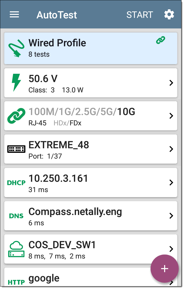
On the Wired Profile screens, you can perform these actions:
-
Tap any of the test result cards, like
 PoE,
PoE,  Link, or
  Switch to open the individual test result screens.
 -
From any individual test screen, tap the settings icon
 to go directly to the settings for the current test.
 -
On the individual test screens, tap blue underlined links to open a Discovery app Details screen showing the selected device or ID.
-
Tap other BLUE LINKS or the blue action overflow icon
 at the bottom of the test results screens for additional actions.
NOTE: You may need to Configure SNMP settings in the Discovery app to see all the available information about a network component, such as name and port information.
NOTE: Blue links and action icons do not appear on every test results screen, and if the active connection is dropped, you may need to rerun the Profile to re-establish link and enable additional actions.
In this Topic
PoE Test Results
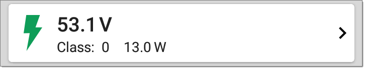
The card for the Power over Ethernet (PoE) test displays the measured Voltage, Class, and Wattage.
Refer to PoE Settings if needed.
Tap the card to open the PoE results screen.
PoE Test Results Screen
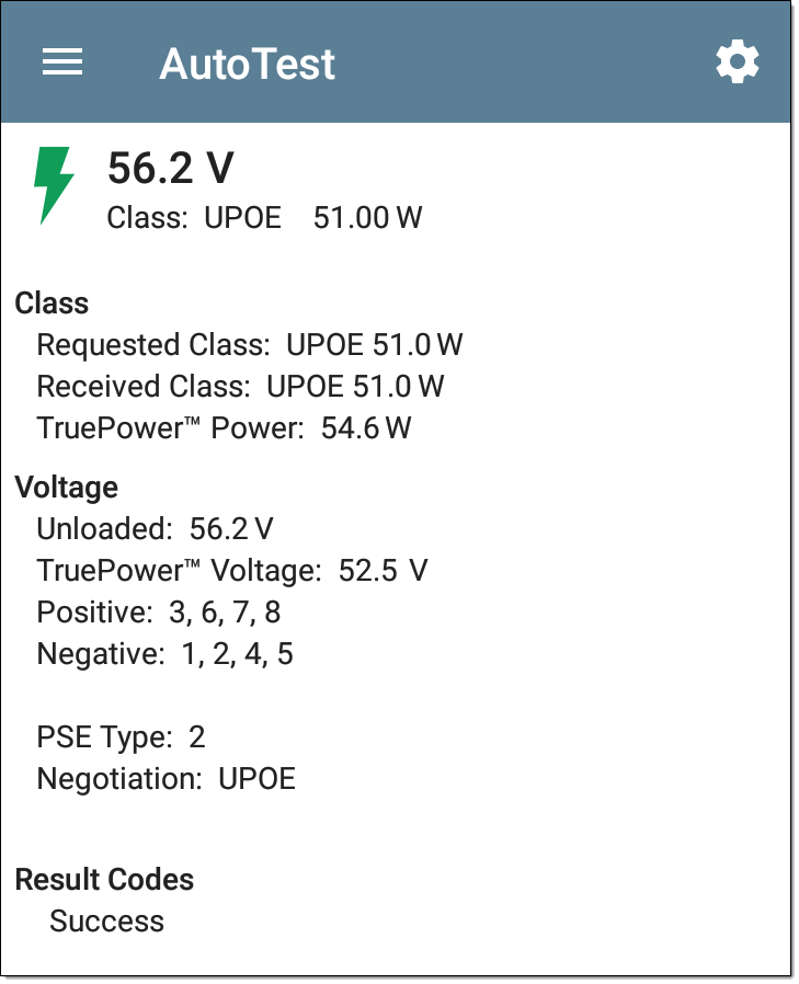
In addition to the information from the PoE card, the PoE test screen shows these results:
Class
Requested Class: Class selected in the PoE test settings
Received Class: Class acknowledgment received from the switch
TruePower™ Power: Measured wattage with load.
NOTE: The PoE card displays additional TruePower™ results only if TruePower is enabled in the Wired Profile PoE Settings.
Voltage
Unloaded: Measured voltage without load
TruePower™ Voltage: Measured voltage with load
Positive: Positive PoE cable pair IDs
Negative: Negative PoE cable pair IDs
PSE Type: Switch's advertised Power Sourcing Equipment (PSE) type. Recognized types are 1 – 4, LTPoE++, Cisco UPOE, and PoE Injectors. PSE supporting UPOE are classified under Type 2. If the type cannot be determined, "1/2" is displayed.
Negotiation: Negotiation status for UPOE and Class 4 (UPOE or LLDP)
Result Codes: Final status of the test (Success or Failure)
Wired Link Test Results
The Wired Link card indicates whether you can connect to an active network switch.
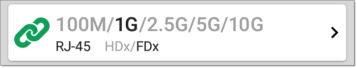
The Link test card for a copper Ethernet connection displays the advertised speed and duplex capabilities in gray text and the detected speed and duplex in black text.
LinkRunner AT can test and display information for link speeds up to
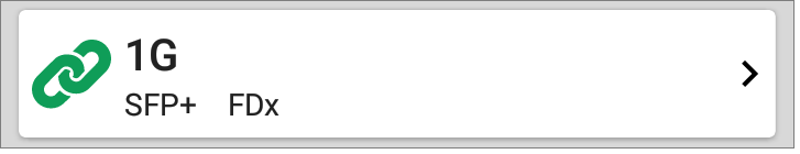
For a Fiber connection, the Link test card shows the connection speed and duplex.
The link icon turns yellow  (displays a Warning) under the following conditions:
-
LinkRunner AT has linked at a speed slower than the maximum advertised speed.
-
The link is using half duplex.
-
For links faster than 1G, LinkRunner AT has detected a minimum SNR value below the set threshold.
Tap the card to open the Link test screen.
Wired Link Test Screen

The Wired Link test screen shows the following:
Speed
Tester Configured: User-selected speed specified in the Wired Connection > Speed/Duplex section of the Wired Profile settings. If Auto is selected for the Speed/Duplex setting, this field will display the speeds supported by your LinkRunner AT.
Link Partner Advertised: Speed capability as reported by the link partner, such as a switch
Actual Speed: Link speed as measured by LinkRunner AT
Duplex
Link Partner Advertised: Duplex capabilities reported by the link partner, such as a switch
Actual Duplex: Duplex in use as detected by LinkRunner AT
RJ-45 Details (Copper)
Rx Pair: Link receive pair
SFP Details (Fiber)
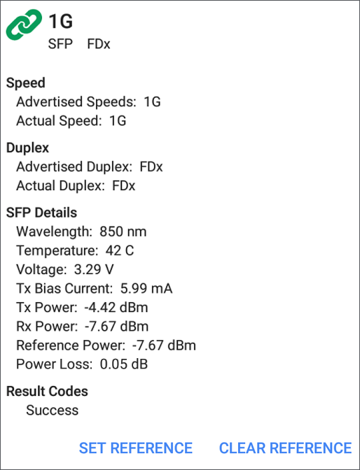
The SFP Details are defined as follows:
Wavelength: Wavelength (in nanometers) at which the fiber connection is operating
Temperature: Temperature in degrees Celsius
Voltage: SFP transceiver power supply voltage (~3.3 V)
Tx Bias Current: Transmitter bias current
Tx Power: Transmitter power
Rx Power: Link receiver power
Reference Power: The user can set a Reference Power by pressing the SET REFERENCE button. This sets the current Rx Power as the reference. The value is saved until cleared by the CLEAR REFERENCE button. (The value is saved across reboots.)
Power Loss: The difference between the current Rx Power and the reference
Results Codes: Final status of the test (Success or Failure)
802.1X Test Results
The 802.1X test card only displays if the 802.1X setting is enabled in the Wired Profile Settings.
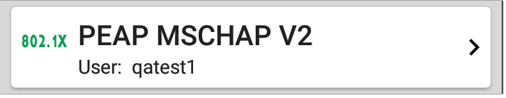
The card shows the EAP type selected in the Wired Connection settings and the username or certificate used. The 802.1X icon turns green if the connection is successful and yellow if 802.1X authentication fails.
802.1X Test Screen
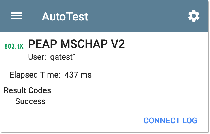
The 802.1X screen also shows the time it took for the authentication process to complete along with Result Codes.
Tap the blue CONNECT LOG link to view the 802.1X Connect Log.
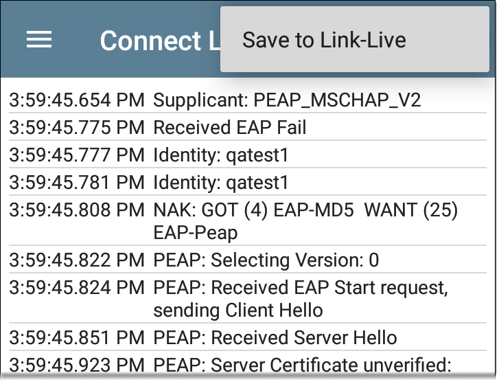
Select the action overflow icon  at the top right on the Connect Log screen to attach the log to its associated AutoTest result on the Link-Live website. You can also attach the Connect Log from the floating action menu
  on the main Wired Profile screen.
VLAN Test Results
The VLAN card only displays if the VLAN setting is enabled in the Wired Profile Settings or if AutoTest detects VLAN-tagged traffic.
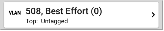
The top line on the VLAN test card shows the configured VLAN settings (image above) or "Untagged" (image below) if VLAN disabled but VLAN-tagged traffic is seen.
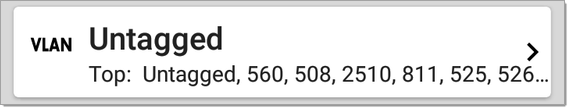
Untagged indicates that no VLAN tag is present in either received or transmitted frames, also referred to as the Native VLAN.
The second line on the VLAN card displays the top VLANs with the most detected traffic.
Tap the card to open the full VLAN screen.
VLAN Test Screen
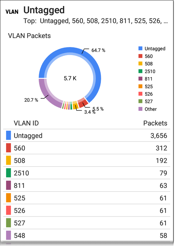
The VLAN test screen displays the real-time traffic the LinkRunner AT detects on the top VLANs. Up to nine VLANs with the highest traffic are displayed as colored portions of the pie chart. The table on the lower part of the VLAN screen lists all the VLANs seen.
Switch Test Results
The results available for the Switch Test are based on Discovery Protocol advertisements and SNMP system group information. SNMP forwarding table data is used to determine the Nearest Switch. See Discovery Settings for SNMP configuration instructions.
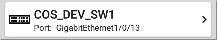
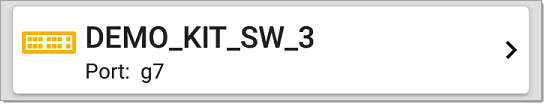
The Switch test card displays the Nearest Switch and the port name. The Switch icon remains black if the test is successful.
- If the LinkRunner AT does not detect any network traffic moving through the switch after 45 seconds, the switch icon turns yellow.
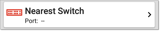
- If the connection is lost while the Wired Autotest is running, the switch icon turns red.
- If the LinkRunner AT was unable to identify the nearest switch, "Nearest Switch Not Found" displays on the Switch card.
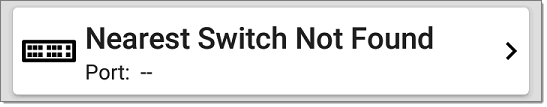
The LinkRunner AT continues to search for the nearest switch, even after the AutoTest completes.
Tap the Switch card to open the full switch results screen.
Switch Test Results Screen
Information on the Switch Test screen is organized by the order in which it was received, either via Discovery Protocol advertisements or SNMP.
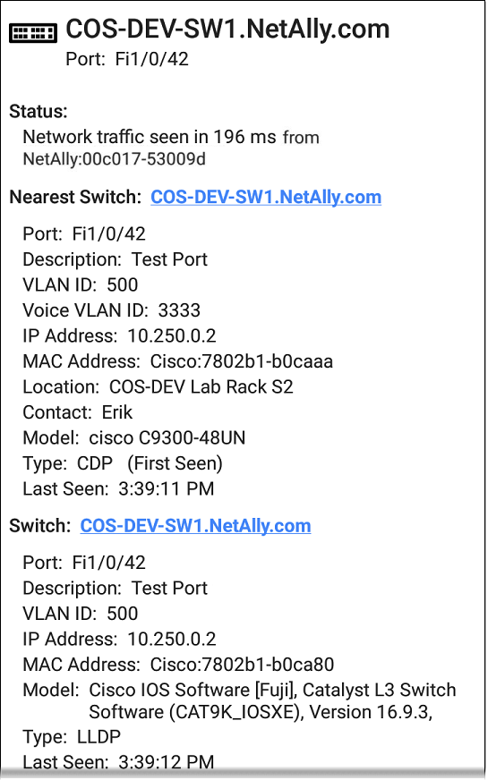
Each section represents a unique port advertisement as defined by protocol type and MAC address.
The switch results screen shows the following data fields:
Status: Time elapsed after link was established before network traffic was received from the switch. The MAC address of the device that sent the packet is also shown.
Nearest Switch: Name of the switch determined to be closest to the LinkRunner AT
Port: Detected Port name
Description: Configured description reported by the switch
VLAN ID: VLAN ID number (if present)
Voice VLAN ID: Voice VLAN ID number (if present)
IP and MAC Addresses: Discovered switch addresses
Location: Configured location reported by the switch. This field only appears if the LinkRunner AT has SNMP access to the Nearest Switch.
Contact: Configured contact person reported by the switch. This field only appears if the LinkRunner AT has SNMP access to the Nearest Switch.
Model: Switch model name and/or number
Type: Discovery Protocol - CDP, LLDP, EDP, FDP, or SNMP. (First Seen) displays next to the protocol type first seen by the LinkRunner AT.
Last Seen: For non-SNMP discovery protocols (CDP, LLDP, EDP, or FDP), the time the advertisement was last received by the LinkRunner AT
Last Updated: For SNMP only, the time the information was gathered from SNMP tables
SNMP information, if available, appears at the bottom of the screen once the discovery process has acquired relevant data.
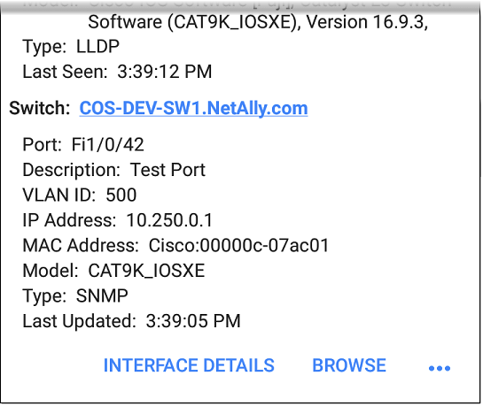
Switch: The Nearest Switch is listed at the top of this section. Other switches seen via advertisements or SNMP are listed below.
Additional Actions
Tap the blue links at the bottom of the switch test results screen to open other apps or tools for the target.
-
Tap INTERFACE DETAILS to open the Interface Details screen for the Switch Port in the Discovery app.
NOTE: The Interface Details action link only appears in the Switch results if LinkRunner AT has current Discovery data, and AutoTest identified the nearest switch and connected interface. -
Tap PING to open the Ping test screen for the switch.
-
Tap the action overflow menu icon
to open an additional menu: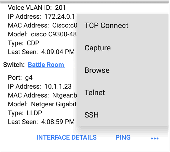
-
Tap TCP Connect to open the corresponding NetAlly apps, populated with the switch's address.
-
Tap Capture to open the Capture app to run a packet capture on the target.
-
Tap Browse to open the Chromium browser pointed to the switch IP address.
-
Tap Telnet to open a Telnet session for the switch IP address.
-
Tap SSH to open a SSH session for the switch IP address.
-
DHCP, DNS, and Gateway Results
See DHCP, DNS, and Gateway Tests
 Target Tests
See the Test Targets topic for information on target test results.
Wired Profile FAB
The floating action button (FAB) on AutoTest Profile screens allows you to add Test Targets to the Profile, as well as attach comments, an image, and an 802.1X connect log to this AutoTest result on the Link-Live website.
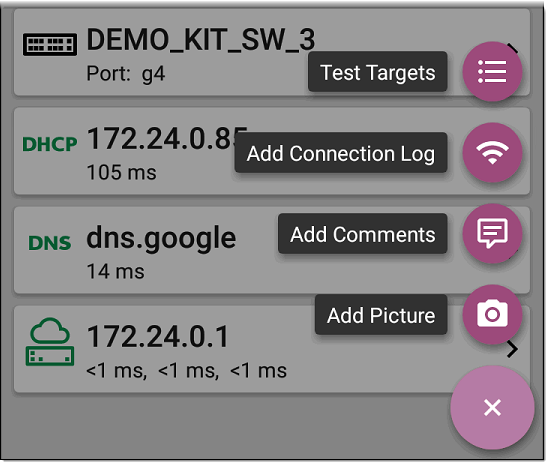
-
The Test Targets option opens the Test Targets screen, where you can add Ping, TCP Connect, HTTP, and FTP target tests to the current profile.
-
Add Connection Log opens a Link-Live upload screen that allows you to custom name the log file before saving to the test result.
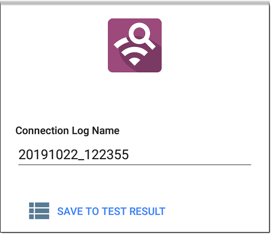
Tap the fields to enter your desired log name and comments, and tap UPLOAD & ATTACH TO RESULT to upload.
-
Add Comments in the floating action menu also opens a Link-Live upload screen where you can enter comments. Tap the fields to enter your desired comments, and tap UPLOAD & ATTACH TO RESULT to upload them.
-
The Add Picture function lets you open the Gallery app to select a photo that is then uploaded and attached to your test result.
See the Link-Live App chapter to learn about Link-Live and uploading.