Wired Profile Settings
These settings control the wired test port connection, PoE tests, the thresholds for Pass/Warning/Fail results, and any user-added test targets.
Tap the settings icon ![]() on the Wired profile screen, or add a new Wired profile, to configure the profile's settings.
on the Wired profile screen, or add a new Wired profile, to configure the profile's settings.
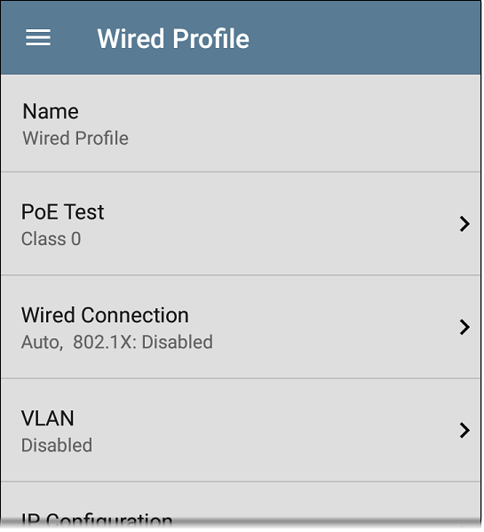
On the Wired Profile settings screen, tap each field described below as needed to configure the profile. Changed settings are automatically applied. When you finish configuring, tap the back button  to return to the profile.
In this Topic
Name
Tap the Name field to enter a custom name for the profile. This name appears on the main AutoTest screen profile card and the Wired Profile screen header.
 PoE Test Settings
Open PoE Test settings to enable or disable PoE and configure the PD Class.
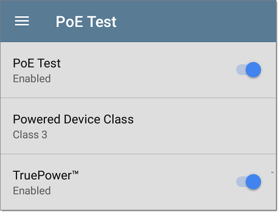
PoE Test
Tap the toggle button to enable or disable the PoE test portion of the current Wired Profile.
Powered Device Class
Tap to select a PoE class setting to match your switch's (or active PoE injector's) available class. LR 10G supports these classes:
- 802.3af Classes 0-3
- 802.3at PoE+ Class 4
- Cisco's UPOE, which can provide up to 51 W
- 802.3bt Classes 5-8
Select Passive PoE Injector if you are using a non-IEEE injector.
NOTE: LR 10G may not receive the total wattage advertised by your switch or injector because of power loss over the cable.
NOTE: LR 10G automatically negotiates Cisco UPOE over LLDP, up to 51 W. LLDP must be enabled on the switch for negotiation to succeed. If the UPOE Class is selected on your LR 10G but LLDP is not enabled on your Cisco switch, negotiation fails.
LLDP
This toggle button appears if Class 4 (25.50 W) is selected. Enable this setting if LLDP is enabled on the switch you are testing. Class 4 LLDP must be enabled on the switch for AutoTest to detect it successfully. If the LLDP setting is enabled but your switch does not support LLDP, negotiation fails.
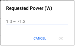
Requested Power (W)
This setting appears if UPOE is selected in the Powered Device Class setting shown above or if the Powered Device Class is set to Passive PoE Injector and TruePower is enabled. Tap to enter a Requested Power other than the default, if needed. If you tap the backspace button on the pop-up number pad and clear the default value, the valid power range is displayed.
TruePower™
TruePower validates that the Switch (Power Sourcing Equipment) and cabling can provide the requested power under load by applying a load equivalent to the selected class to mimic a Powered Device (PD). Tap the toggle button to enable the TruePower feature.
General Settings that Affect PoE
See the Wired section in General Settings for a description of the Test PoE before Link setting.
 Wired Connection Settings
Open Wired Connection settings to configure speed/duplex, link persistence, user-defined MACs, 802.1X settings
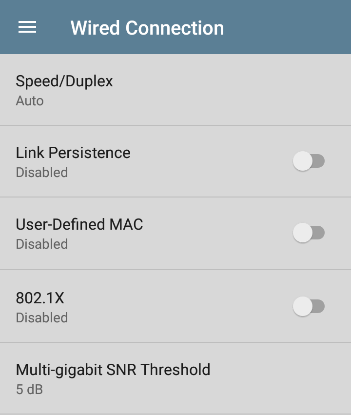
Speed/Duplex
Tap to select the speed and duplex option that you want to test your network against. The default is Auto negotiation.
When speed is set to Auto, LR 10G auto-negotiates to the highest possible speed/duplex supported by the link partner. You can select a fixed speed/duplex for the copper interface. For 10 and 100 Mbps, you can optionally force the speed and duplex.
This setting does not force the link speed/duplex on the fiber interface, but does control which speed is attempted first when using a multi-rate SFP. As a result, this setting can enable the test unit to connect faster via fiber.
Link Persistence
Link Persistence controls tester behavior before linking and after link goes down. The default setting for Link Persistence is disabled.
Link Persistence and Establishing Link: When enabled, there is no timeout on how long the tester will wait for link to be established. When disabled, the link step will fail if not successful in 25 to 30 seconds.
When using a multi-rate SFP to link on fiber, enabling Link Persistence limits linking to one speed. To link at 1000BASE-X, the Speed/Duplex setting must be set to 1 G FDx. Otherwise, the tester will only attempt to link at 10GBASE-R. When using a single-rate SFP, the Speed/Duplex setting has no effect.
Link Persistence and Link Dropping: When enabled and link drops, the unit attempts to relink. When disabled and link drops, the test profile is considered done and no further links are attempted until a Wired Profile is run again.
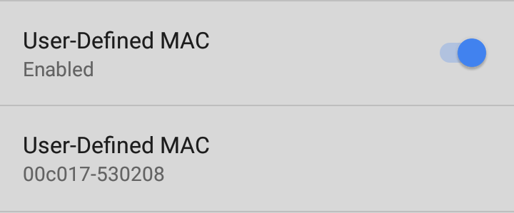
User-Defined MAC
This feature can help with tasks such as testing ACL lists (for example, finding out if specific MAC addresses are allowed on the network) or determining if specific IPv4 addresses should be assigned to specific MAC addresses.
-
Tap the toggle field to enable a user-defined MAC for the LR 10G. This displays the current user-defined MAC definition. (If you have not previously provided a definition, the field shows the factory default MAC address.)
-
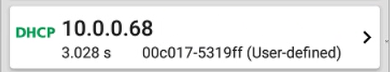
To enter a new definition, tap the User-Defined MAC definition field, enter a new definition, and then tap OK. When enabled, (User-defined) appears next to the MAC address on the About screen and on relevant test result screens.
802.1X
Tap the toggle field to enable wired 802.1X authentication in the current Profile. Enabling this setting also enables an 802.1X test card on the Wired AutoTest results screen.
The following settings appear when 802.1X authentication is enabled. Enter all necessary credentials, such as EAP type, username and password, or certificate.
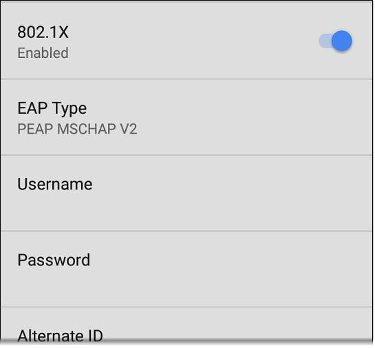
EAP Type
Tap to select a different EAP type if needed. The default is PEAP MSCHAP V2.
Certificate
This setting appears if one of the following EAP types is selected in the setting above: EAP TLS, PEAP TLS, or TTLS EAP TLS.
See How to Import a Certificate.
Username
This field appears along with multiple authentication types. Tap the Username field to enter your username.
Password
This field appears along with multiple authentication types. Tap the Password field to enter the network password.
Alternate ID
Enter an Alternate ID if necessary. This is an Advanced Authentication setting.
Multi-gigabit SNR Threshold
When a Wired Profile links at speeds higher than 1 Gbps, a table appears on the Link Test screen showing Multi-gigabit Details. This threshold grades SNR measurements on the four twisted pairs. A Minimum SNR below the selected threshold displays a yellow warning condition. The default is 5 dB. If more than one signal is below the Minimum SNR, the signal with the lowest value is shown.
VLAN Settings
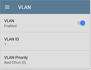
Tap to open the VLAN settings screen. Slide the toggle to the right to enable VLAN testing. Enabling this setting also enables a VLAN test card on the Wired AutoTest results screen. Once enabled, VLAN ID and VLAN Priority fields appear. Tap these fields to open a pop-up number pad and enter the correct ID and priority. Tap OK to save them.
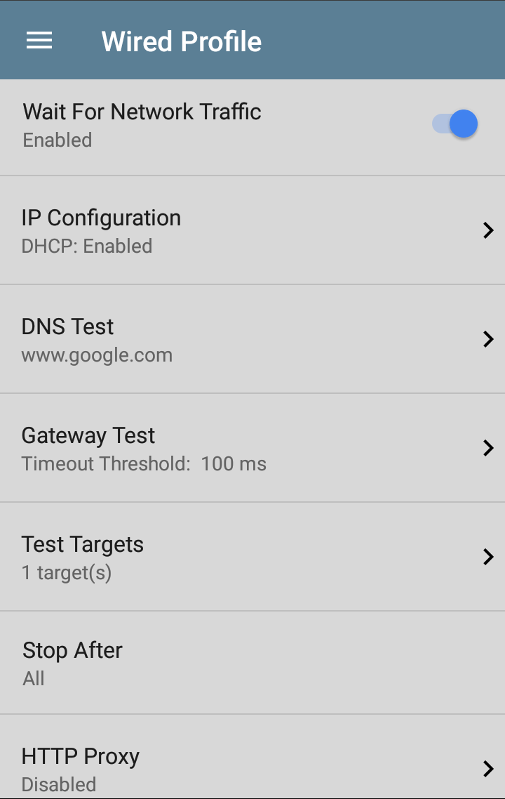
Wait For Network Traffic
Wait for Network Traffic controls whether there is any delay after link comes up before proceeding to the next step. When enabled there is a delay waiting for packets to be forwarded from the network by the nearest switch. This is useful for switches that are configured to search for networking loops prior to forwarding traffic. On networks with very little traffic, you may choose to disable this delay. The maximum time to delay is 45 seconds.
DHCP, DNS, and Gateway Settings
See DHCP, DNS, and Gateway Tests.
 Test Targets
Tap the Test Targets field to open the Test Targets screen and add custom
Stop After
This setting directs the Wired Profile to stop testing after the selected test step (Link, Switch, DHCP, DNS, Gateway, or All). The excluded test cards do not appear on the Profile results screen.
HTTP Proxy
The Proxy control lets you specify a proxy server through which the LR 10G establishes a network connection. In AutoTest, these settings are used when HTTP Proxy is enabled in an HTTP or FTP Test Target.
To use the proxy settings with a web browser, run the Profile, and then open the web browser while the unit remains linked.
Open the HTTP Proxy screen to enable proxy settings.
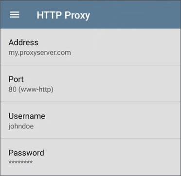
Tap each field to open a pop-up keyboard and enter the appropriate Address (you can enter a proxy name or an IPv4 address), Port (set to match the proxy port), Username, and Password. Tap OK to save your entries.