You just completed a 25G/40G/50G/100G upgrade. The links are up, traffic is flowing, and your dashboard shows zero errors. Time to move on to the next project, right? Not necessarily. In the world of the 100G Ethernet standard, a clean dashboard does not always mean a clean physical layer.
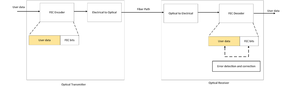
Forward Error Correction (FEC) plays a massive role in modern high-speed networks. While it is essential for keeping your links alive, it might also be obscuring severe physical layer issues.
This guide breaks down why FEC is mandatory for 100GbE, how it affects your network performance, and why you need to pay attention to what it might be hiding.
Why 100G Networks Require FEC
FEC is a fundamental requirement for 100G Ethernet networks due to high signaling rates (25G+ bps per lane) and PAM4 modulation. At these speeds, signal integrity alone is simply not sufficient to deliver acceptable bit error rates (BER) for error-free transmission.
FEC addresses this physics problem by transmitting additional bits alongside every block of user data. This redundancy allows the receiver to detect and mathematically correct bit errors on the fly.
The IEEE defines the requirements for FEC as mandatory or optional based on the physical layer specification – whether you are using Single-mode fiber (SMF), multimode fiber (MMF), or Direct Attach Copper (DAC) – and the modulation type (NRZ, PAM4, CWDM).
Understanding Reed-Solomon and FEC Types
There are multiple types of FEC, but the IEEE specifically relies on Reed-Solomon error correction for high-speed Ethernet.
Reed-Solomon is specified by a pair of numbers representing the total transmitted block size and the data block size. For example, RS(528, 514) signifies that the transmitter sends 528 total bits containing 514 data bits. The extra 14 bits provide the redundancy the receiver needs to correct errors.
Yes, transmitting additional bits adds latency. However, this microsecond delay is generally accepted because the latency impact of dropping and re-transmitting a frame due to a bad FCS (Frame Check Sequence) is significantly worse.
The choice between FEC types is largely determined by the modulation type (NRZ or PAM4). Table 1 presents an overview of RS-FEC usage across various Ethernet standards.
| Feature | RS(528, 514) | RS(544, 514) |
| Common Name | KR-FEC | KP-FEC |
| Modulation | NRZ (Non-Return to Zero) | PAM4 (Pulse Amplitude Modulation) |
| Data Rate | 25G / 100G NRZ links | 50G / 100G / 200G / 400G |
| Parity Symbols | 14 symbols | 30 symbols |
| Error Correction | Up to 7 symbols | Up to 15 symbols |
| Latency | Lower (~87ns) | Higher (~112ns) |
The FEC Terminology Guide
Switch vendors and technical documents use various terms to describe FEC implementations, often interchangeably. This can make reading a switch manual feel like translating ancient Greek.
Here is a breakdown to help you decode sentences like: “The host system is required to enable RS(544,514) FEC (‘KP4 FEC’) in accordance with clause 91.”
BASE-R FEC:
- FEC(2112,2080) (The mathematical definition)
- Clause 74 FEC (The IEEE standard section)
- Fire Code or FC-FEC (The more common term)
RS(528,514):
- RS(528, 514) (The mathematical definition)
- Clause 91 FEC (The IEEE standard section)
- KR4-FEC or KR-FEC (The more common and precise term)
- RS-FEC (Often used generically, but usually implies KP4 or KR4)
RS(544,514):
- RS(544, 514) (The mathematical definition)
- Clause 91 FEC (The IEEE standard section)
- KP4-FEC or KP-FEC (The more common and precise term)
- RS-FEC (Often used generically, but usually implies KP4 or KR4)
FEC NONE:
- FEC Disabled
- no-FEC
The FEC Secret Decoder Ring
The tables below provide a cheat sheet for configuring the correct FEC settings on your network devices.
Start with your transceiver or optical module type, look up the required FEC type, and cross-reference it with the IEEE standard. Your switch documentation will refer to either the FEC Type or the IEEE reference for configuration.
| Module Type | FEC Type | Reqd | IEEE 802.3-2022 Reference |
| 100GBASE-CR2 | RS(544,514) | yes | PMD clause 136, FEC clause 91 |
| 100GBASE-CR4 | RS(528,514) | yes | PMD clause 92, FEC clause 91 |
| 100GBASE-DR, FR1, LR1 | RS(544,514) | yes | PMD clause 140, FEC clause 91 |
| 100GBASE-ER4, LR4 | no-FEC | PMD clause 88 | |
| 100GBASE-SR2 | RS(544,514) | yes | PMD clause 138, FEC clause 91 |
| 100GBASE-SR4 | RS(528,514) | yes | PMD clause 95, FEC clause 91 |
| 100GBASE-ZR | RS(528,514) SC-FEC | no / yes | PMD clause 154, FEC clause 91, SC-FEC clause 153 |
| PHY Type | FEC Type | Reqd | IEEE 802.3-2022 Reference |
| 50GBASE-BR10/20/40 (D/U) | RS(544,514) | yes | PMD clause 160, FEC clause 134 |
| 50GBASE-CR | RS(544,514) | yes | PMD clause 136, FEC clause 134 |
| 50GBASE-ER, FR, LR, SR | RS(544,514) | yes | PMD clause 139, FEC clause 134 |
| PHY Type | FEC Type | Reqd | IEEE 802.3-2022 Reference |
| 40GBASE-CR4 | BASE-R | no | PMD clause 85, FEC clause 74 |
| 40GBASE-ER4 | no-FEC | PMD clause 87 | |
| 40GBASE-FR | no-FEC | PMD clause 89 | |
| 40GBASE-LR4 | no-FEC | PMD clause 87 | |
| 40GBASE-SR4 | no-FEC | PMD clause 86 |
How FEC Impacts 100G Link Quality
The functional quality of a fiber link is defined by its bit error ratio (BER). The BER encompasses the overall effects of physical parameters like reflectance, loss, and dispersion. Simply put, it is the ratio of errored bits to the total number of transmitted bits.
A single bit error can severely impact throughput because it causes a frame error. Applications running over TCP will experience increased latency due to the re-transmission of that lost frame.
FEC reduces an otherwise unacceptable bit error ratio to a functional value by correcting errors in transit.
| Pre-FEC BER: Raw link quality | Post-FEC BER: User experienced performance |
| 10^-3 to 10^-4 | < 10^-12 to 10^-15 |
| Unacceptable | Acceptable |
While FEC saves your throughput, it does introduce minor latency and jitter. If latency is highly critical for your application, be aware that store-and-forward switches will be much less affected by this than cut-through switches. For a detailed analysis on this specific impact, see FEC Killed the Cut-Through Switch.
Is FEC Masking Issues in Your Network?
Here is the catch: RS-FEC converts a link with unacceptable quality into one with acceptable quality. This means raw link quality issues are actively masked.
FEC hides the shrinking margin between error-free transmission and total failure. You could have a dirty MPO or MTP connector, a failing optic, or degraded fiber, and your network will show no outward signs of distress – until the FEC algorithm can no longer keep up and the link drops entirely.
Pro Tip:
Do not just look at link status. Keep track of the trends in your FEC counters (corrected and uncorrected errors). If the number of corrected errors is stable, your media is stable. A steadily increasing number of corrected errors is a massive red flag indicating that your physical infrastructure is degrading.
FAQ
What is forward error correction (FEC)?
Forward error correction is a method that adds redundant bits to a transmitted data stream, allowing the receiver to detect and correct errors without requesting a re-transmission.
Why is FEC needed?
FEC allows for longer fiber cable runs in high-speed networks (25G/40G/50G/100G) that are highly sensitive to media quality problems and signal degradation.
What are the common types of FEC for 100G Ethernet?
The dominant type for 25G to 100G networks is Reed-Solomon FEC (RS-FEC). Another variant used in specific older or lower-speed applications is Firecode / BASE-R FEC.
Does FEC add latency?
Yes. The mathematical processing required to correct errors adds a small amount of latency. Depending on your specific application (like high-frequency trading), this added latency may be critical or entirely insignificant.